SO-101 是一套主从式桌面机械臂:人手拖动主动臂(Leader),从动臂(Follower)同步复现动作。两条机械臂各有 6 个舵机,主动臂末端是握把和扳机,从动臂末端是夹爪。后面的数据采集、ACT 和 VLA 实验,都建立在这套硬件上。
最开始以为搭机械臂和拼模型差不多,把舵机塞进 3D 打印件,再把螺丝拧紧就行。真的把十二个舵机、两块控制板和一桌零件铺开后,才发现装配只是表面工作。舵机有没有回到中位、编号是否对应关节、线从哪里穿、供电有没有接错,都会在后面的遥操作和真机推理里重新找上门。
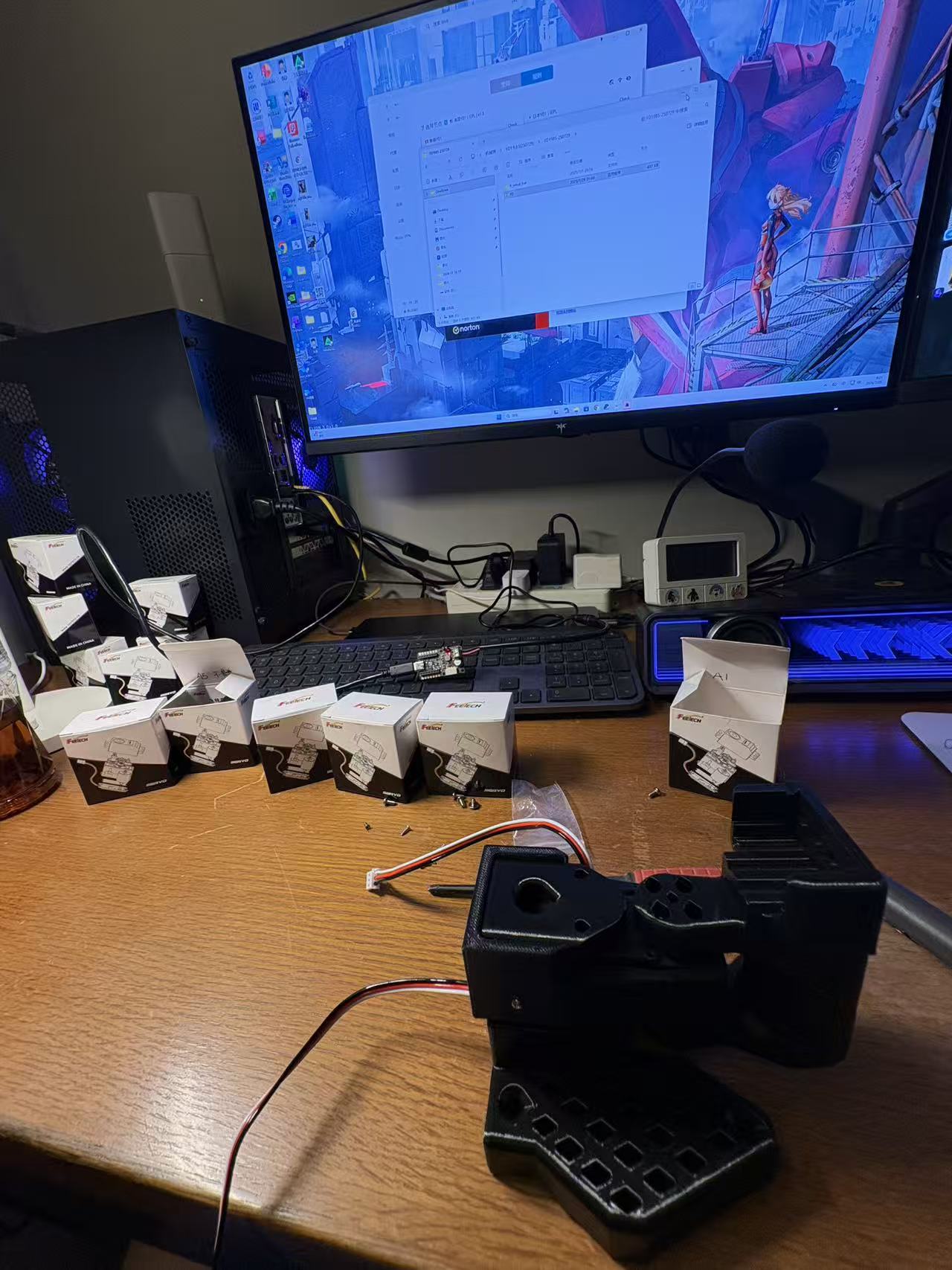
装配开始前的一桌零件。十二个舵机需要先按主从臂、型号和关节位置分开,装错一个,往往就要拆回去。
完整流程先摊开
从散件到可以遥操作,大体要经过这条链路:
开箱清点 → 清理 3D 打印支撑 → 区分舵机型号 → 安装舵盘 → 单舵机通电检查 → 中位校准和 ID 编号 → 组装主动臂 → 组装从动臂 → 检查供电与总线 → LeRobot 校准 → 小范围遥操作。
三张本次搭建实拍只覆盖了其中几个阶段,下面再穿插九张知识库里的教程参考图,把容易装错、又很难只靠文字说清楚的细节补全。不同批次的 3D 打印件、舵机和控制板可能会调整,真正接电时仍然要以手里的型号标签和接口标识为准。
1. 先把零件清点清楚
散件套装里主要有两套 3D 打印结构件、十二个舵机、主动/被动舵盘、舵机线、两块控制板、电源适配器、自攻螺丝、M3 螺丝和安装控制板用的铜柱。工具不复杂,大小合适的十字螺丝刀必不可少;电动螺丝刀能省很多时间,但最后收紧最好仍用手控制力度。上电检查还需要一根数据线,手边有万用表会更稳妥。
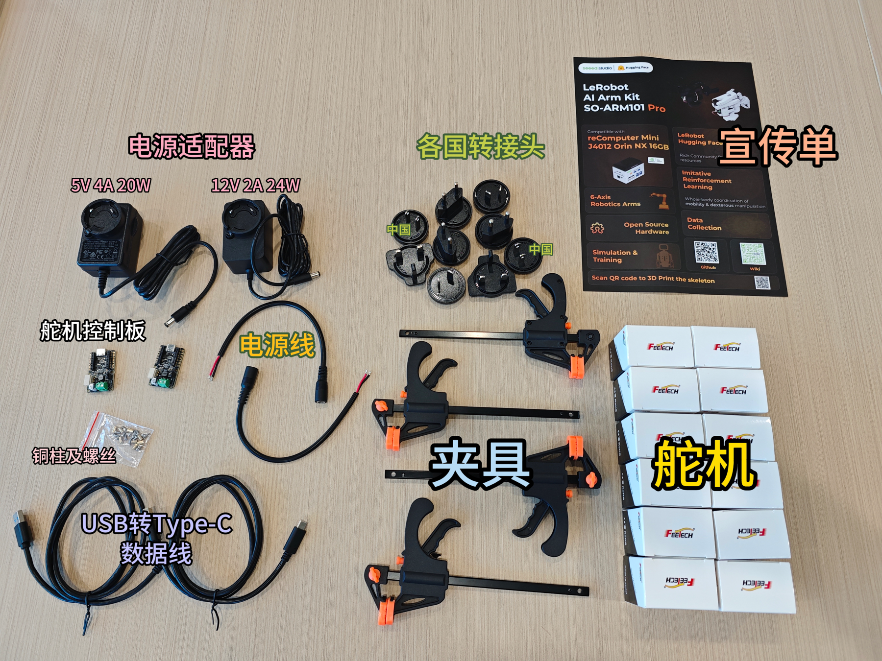
先按类别把所有零件摊开清点,缺件和拿错规格都会在这一步暴露。教程参考图,来源:同济子豪兄、朱耀晖、刘越。
拆开打印件后,先检查所有孔、槽和网格。残留的打印支撑要在装舵机之前清掉,尤其是舵盘周围的小孔和藏线槽。孔位不通时不要直接用螺丝硬顶,先用螺丝刀或小锉刀把支撑处理干净,否则很容易把自攻螺丝拧歪。
知识库记录的这套舵机配置如下:
| 机械臂与关节 | 舵机小型号 | 额定电压 | 减速比 | 数量 |
|---|---|---|---|---|
| 主动臂 2 号关节 | C001 | 7.4V | 1:345 | 1 |
| 主动臂 1、3 号关节 | C044 | 7.4V | 1:191 | 2 |
| 主动臂 4、5、6 号关节 | C046 | 7.4V | 1:147 | 3 |
| 从动臂 1 至 6 号关节 | C047 | 12V | 1:345 | 6 |
主动臂需要被手拖着完成示教,所以不同关节用了不同减速比;从动臂负责带动机械结构和夹爪,六个关节统一使用扭矩更大的版本。十二个外壳非常相似,清点后最好按“主动臂/从动臂 + 关节编号”分开放回盒子。
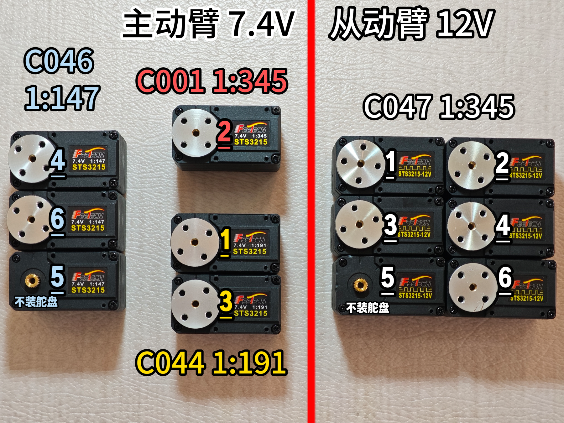
舵机外观几乎一样,装配前要同时核对小型号、电压和关节编号。教程参考图,来源:同济子豪兄、朱耀晖、刘越。
2. 舵机要在装进去之前完成配置
每个舵机的主轴齿轮一侧安装主动舵盘,另一侧安装被动舵盘。舵盘压紧以后,再逐个做通电检查,不要一开始就把十二个舵机串在同一条总线上。
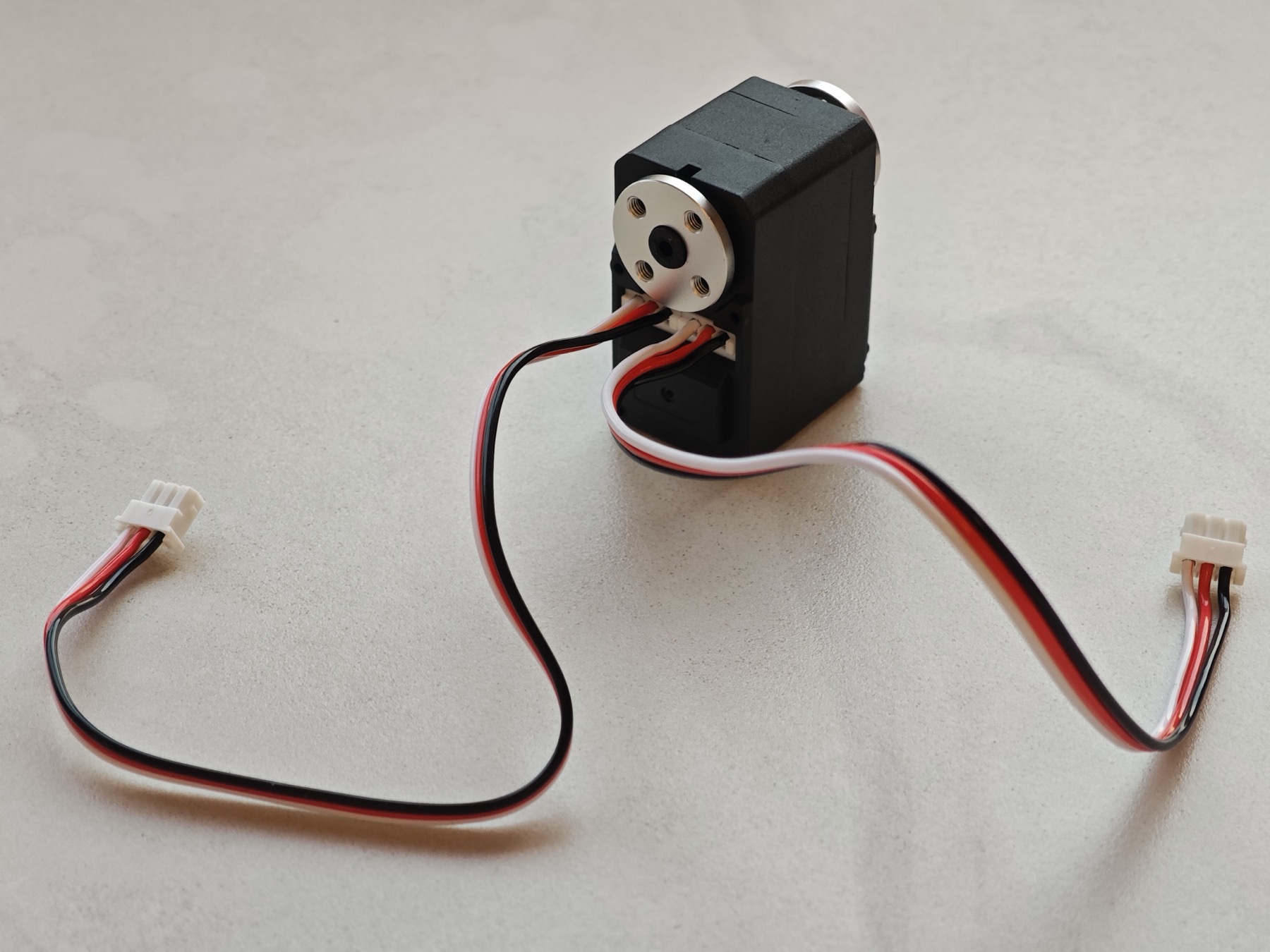
装进结构件前先把舵盘和需要的两根总线接好,之后狭窄空间里会很难补线。教程参考图,来源:同济子豪兄、朱耀晖、刘越。
这次使用飞特调试工具完成了下面几步:
- 用 USB 数据线连接舵机控制板和电脑,只接一个舵机。
- 按控制板和电源标识接好正负极,确认没有散开的金属线头。当前套件里,主动臂和从动臂使用不同规格的适配器,不能混插。
- 在调试工具里选择对应串口,以 1,000,000 波特率打开连接并搜索 STS3215。
- 小范围转动或扫描,确认舵机能够正常响应。
- 把当前位置写成中位,再把 ID 写成它所在机械臂的 1 至 6 号。
- 断电、拔线,在舵机和盒子上同时写好编号,再处理下一个。
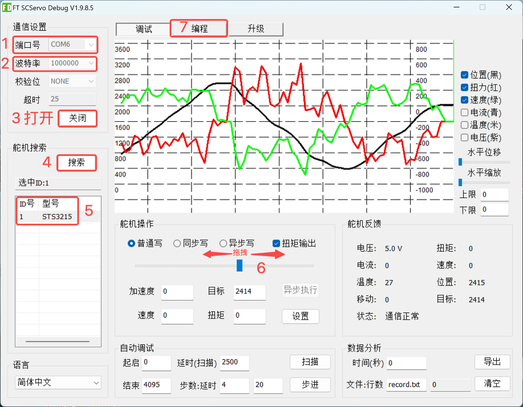
飞特调试工具用于逐个搜索舵机、检查响应并写入中位与 ID。教程参考图,来源:同济子豪兄、朱耀晖、刘越。
两条机械臂都使用 1 至 6 号 ID,因为它们分别连接各自的控制板。这里最怕的是漏写、写重或把主动臂舵机放进从动臂盒子。舵机装进结构件后,标签、接口和舵盘都会被挡住,那时再返工会麻烦很多。
3. 从底座开始组装主动臂
主动臂的安装顺序从底座一路走到握把:
- 1 号舵机与底座: 1 号舵机预留两根线,一根向下连接控制板,另一根沿结构件向上连接 2 号舵机。
- 2 号关节与大臂: 固定 1 号舵机套筒和 2 号支架,再把大臂装到 2 号舵机两侧的舵盘上。
- 3 号关节与小臂: 3 号舵机连接大臂和小臂,安装时同时确认舵盘处在中位附近,不要让关节一开始就顶到机械限位。
- 4 号腕部: 装入 4 号舵机和套筒,舵机线沿槽向末端继续传递。
- 5、6 号关节: 5 号舵机藏在窄套筒里,一根线返回 4 号,另一根继续接 6 号。先走线、再把舵机滑进套筒,最后固定螺丝。
- 握把、扳机和控制板: 6 号舵机连接扳机,握把固定在支架上;控制板通过铜柱装到底座,最后接入 1 号舵机、电源和 USB 数据线。
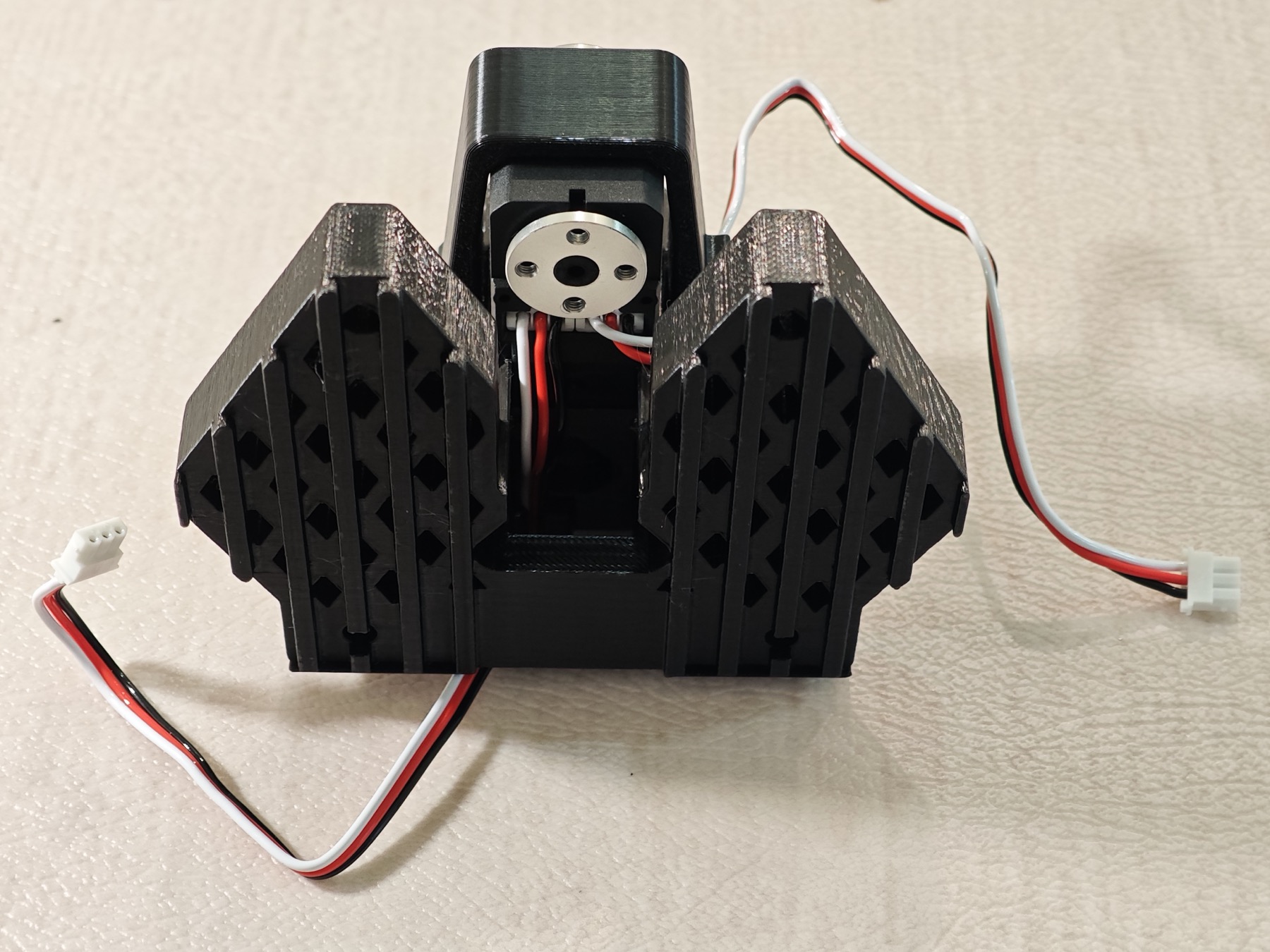
1 号舵机的一根线接控制板,另一根继续向上串联 2 号关节。教程参考图,来源:同济子豪兄、朱耀晖、刘越。
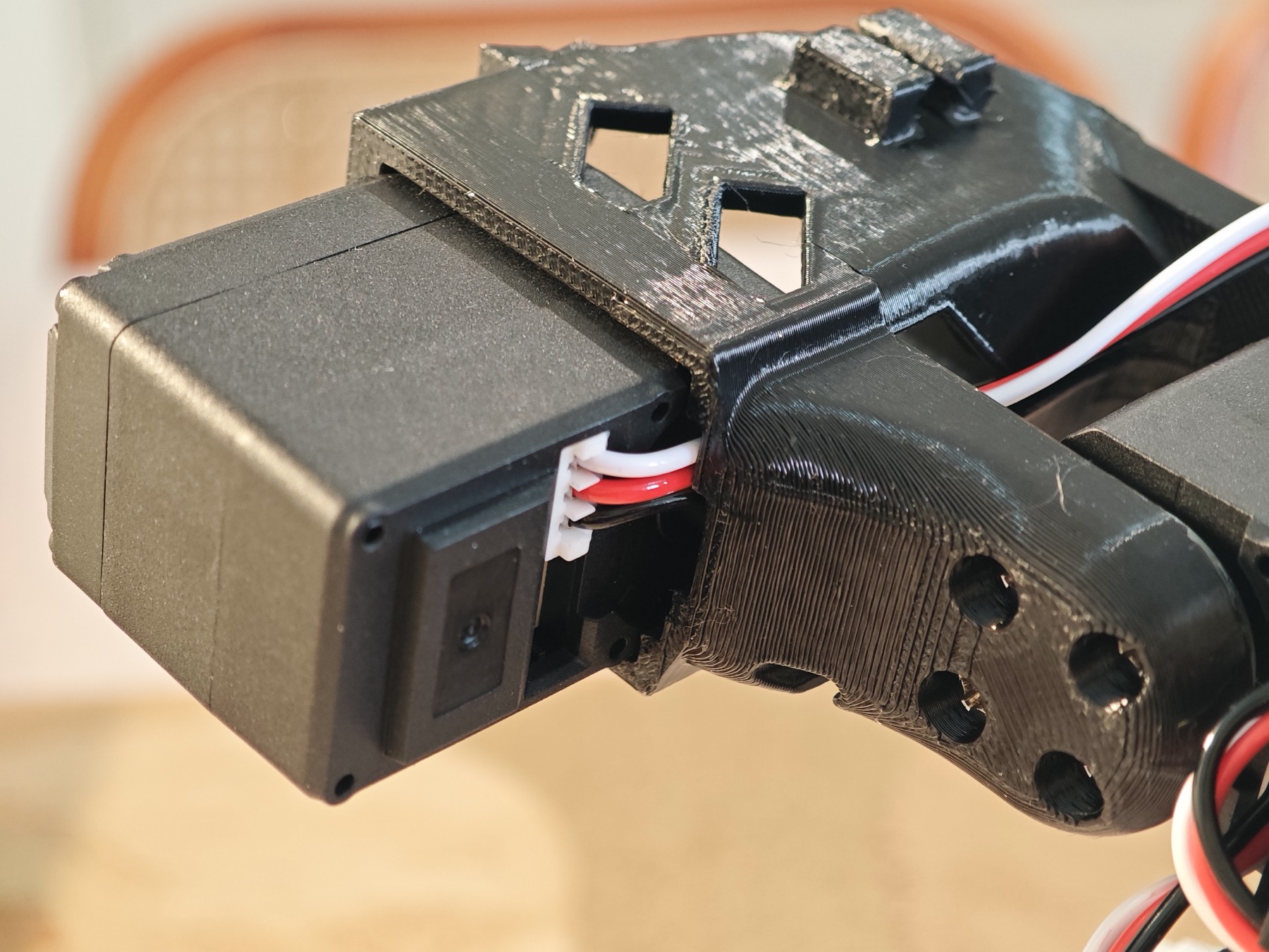
腕部空间很窄,舵机线必须先落入槽内,再合上结构件。教程参考图,来源:同济子豪兄、朱耀晖、刘越。
最容易返工的是第 5 步。线没有提前落进槽里,或者套筒方向装反,等螺丝拧紧后几乎没有操作空间。这里不能靠蛮力硬塞,固定前还要转动腕部检查线缆会不会被夹住。
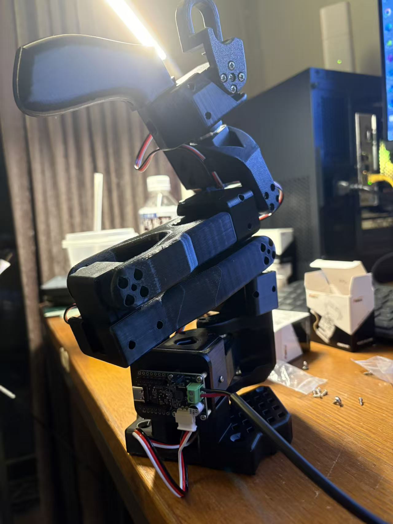
黑色主动臂已经基本成形。末端的握把和扳机用于示教,底部控制板连接整条舵机总线。
4. 再按同样的骨架组装从动臂
从动臂的 1 至 5 号关节沿用同一套骨架:底座、2 号支架、大臂、3 号关节、小臂、4 号腕部和 5 号套筒依次连接。每装完一个关节,都要把下一段舵机线留出来,而不是等结构闭合后再想办法穿线。
真正不同的是末端:
- 把 5 号舵机的两根线分别接向 4 号和 6 号关节,确认套筒方向后再固定。
- 先把 6 号舵机装进夹爪固定件并锁紧自攻螺丝。
- 如果使用腕部相机支架,要在夹爪活动件之前滑入并固定;顺序反了会挡住其中一个舵机螺丝孔。
- 将夹爪固定部分装到 5 号舵盘,将活动夹爪装到 6 号舵机两侧的舵盘。
- 手动检查夹爪的开合范围、舵盘是否松动,以及相机线和舵机线有没有被拉紧。
- 最后把从动臂控制板装到底座,连接 1 号舵机和对应电源。
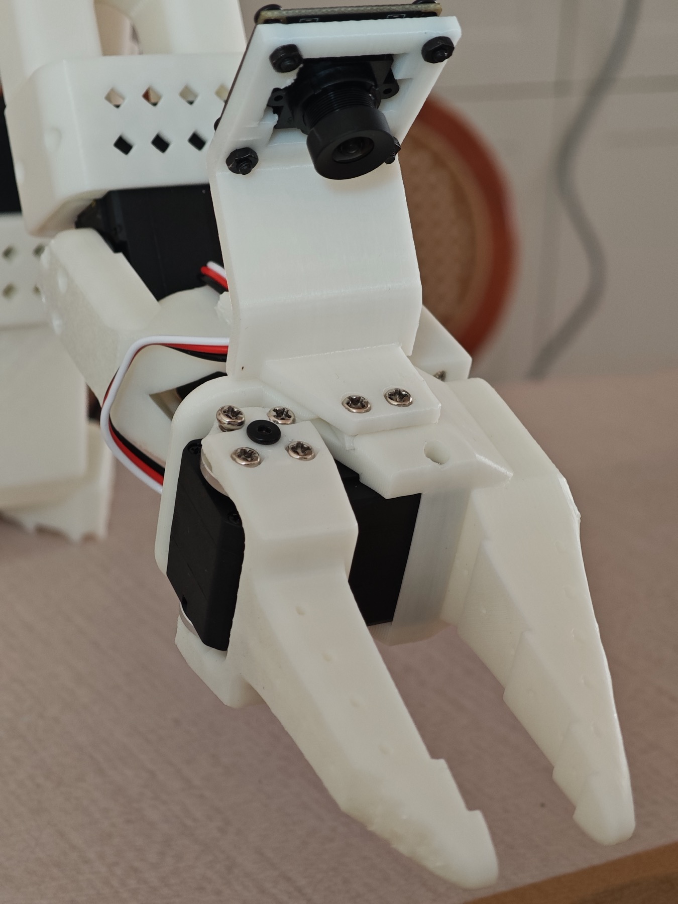
腕部相机支架要在夹爪结构完全闭合前装好,否则会挡住螺丝孔。教程参考图,来源:同济子豪兄、朱耀晖、刘越。
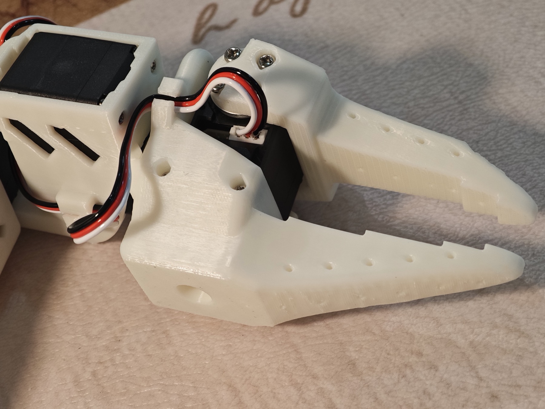
夹爪安装后仍要给舵机线留下活动余量,避免开合时反复拉扯接头。教程参考图,来源:同济子豪兄、朱耀晖、刘越。
主动臂末端是握把和扳机,从动臂末端是夹爪和腕部相机位。两边看起来很像,却不能复制同一套接线和供电。当前套件的主动臂是 7.4V 舵机,从动臂是 12V 舵机;适配器、控制板和舵机标签要在每次上电前重新核对。
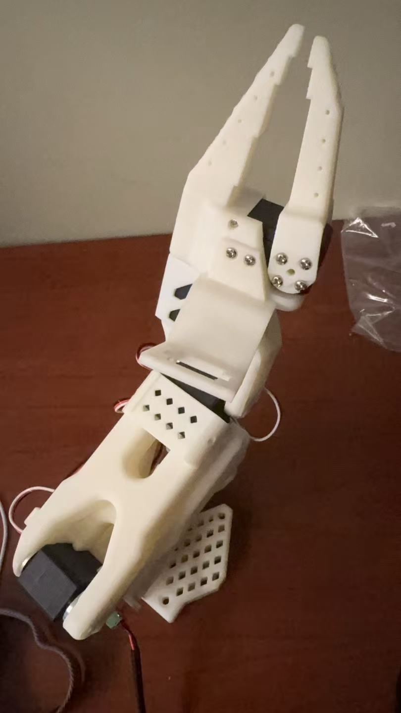
白色从动臂完成装配。末端是夹爪,之后还会加上腕部相机,用于采集第一视角画面。
5. 上电前后各检查一次
第一次检查在断电状态下完成:
- 从夹爪或扳机一路检查到底座,确认自攻螺丝、M3 螺丝和舵盘没有松动。
- 查看每段舵机线是否落在槽内,有没有被套筒压住,转动关节时会不会拉扯接头。
- 核对控制板电源正负极和适配器规格,确认裸露金属丝没有互相接触;有万用表时先测控制板输出电压。
- 小心转动各关节,排除明显的结构卡死。从动臂减速比较大,本来就比主动臂难拖动,不能只凭手感轻重判断是否装错。
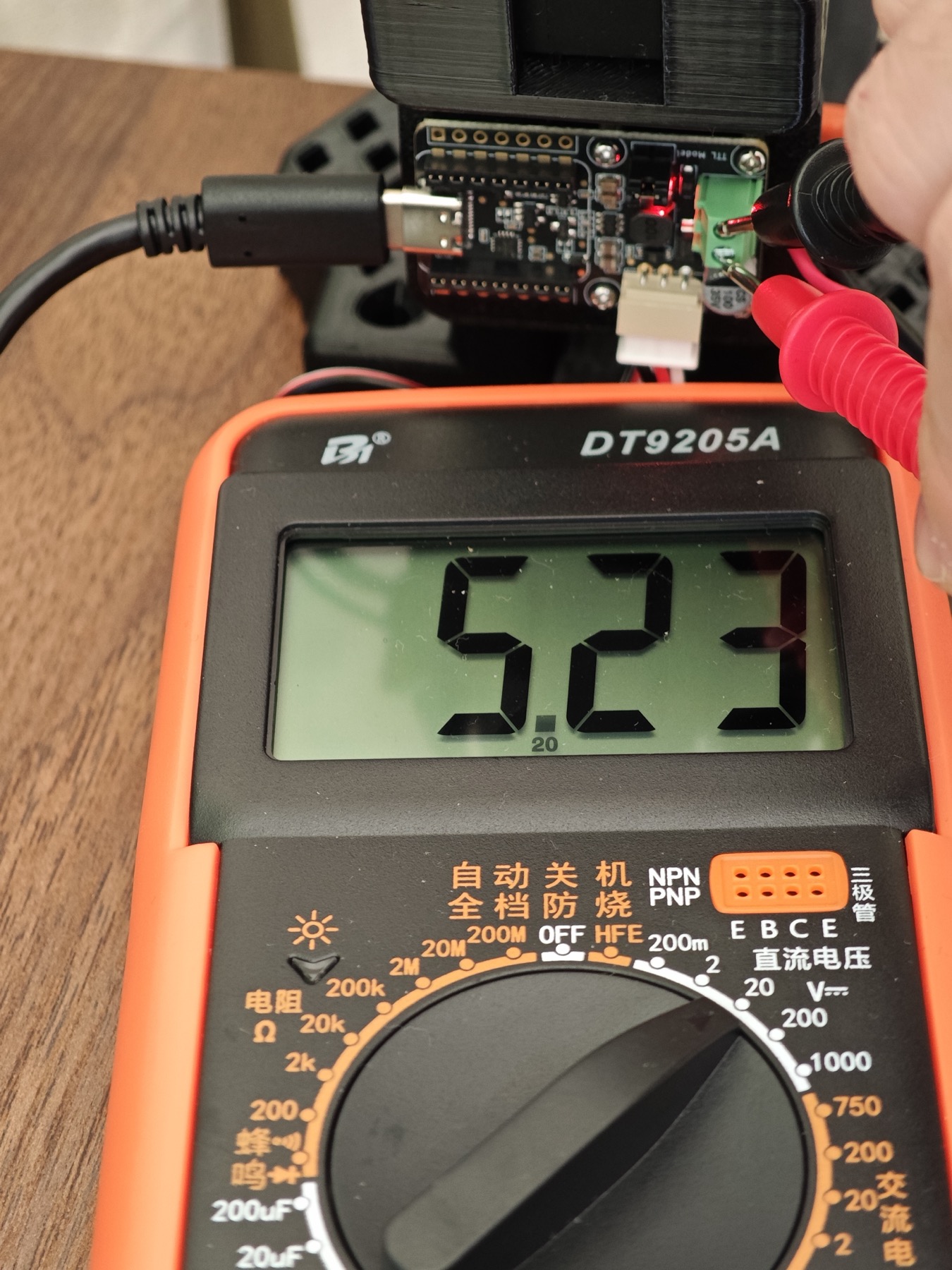
第一次接舵机前先测控制板输出,确认极性和电压与对应机械臂一致。教程参考图,来源:同济子豪兄、朱耀晖、刘越。
第二次检查在通电后完成。先用飞特调试工具扫描总线,主动臂和从动臂分别确认 1 至 6 号舵机都能被找到,而且没有重复 ID。之后只做小范围动作,逐个观察方向、中位、异响和线缆状态,不要第一次上电就让整条机械臂跑满行程。
6. 从“装好了”到“可以遥操作”
机械结构通过检查后,还要把两块控制板分别接入运行 LeRobot 的电脑,识别主动臂和从动臂对应的串口。随后分别完成两条机械臂的软件校准,记录各关节的有效范围和中位,并保存各自的校准文件。
第一次遥操作仍然只做很小的动作:轻推主动臂的单个关节,看从动臂是否按同一方向响应,再检查扳机与夹爪的开合映射。六个关节分别确认后,才进行连续动作。到这里,整条搭建链路才真正闭合:零件已经装好,舵机能够通信,主从映射也可以受控运行。
这一步给后面的调试划了一条线
几天后,这套机械臂开始采集示教数据,并进入 ACT 的训练和真机推理。到了那个阶段,机械臂抖动或动作异常不一定来自模型,也可能是舵机 ID、中位、供电、接线或舵盘松动。搭建时把这些检查结果固定下来,后面排查时才能先把硬件问题排除掉。
接下来的过程记录在复现 ACT:让 SO-101 用 9 条示教学会抓东西里。
参考与图片说明
搭建步骤主要参考同济子豪兄、朱耀晖和刘越整理的 LeRobot / SO-ARM 101 教程。文中三张阶段照片为本次搭建实拍,另外九张用于解释装配细节的参考图来自上述教程,均已在图注中标明原作者。
SO-101 is a tabletop leader-follower robot system. A person moves the leader arm by hand, and the follower reproduces the motion. Each arm uses six servos. The leader ends in a handle and trigger, while the follower carries the gripper. All later data collection, ACT, and VLA experiments depend on this hardware.
At first, the build looked similar to assembling a model kit: fit the servos into the 3D-printed parts and tighten the screws. Once twelve servos, two controller boards, and a desk full of parts were laid out, the harder part became clear. Servo centering, joint IDs, cable routing, and power checks would all return as control problems later if they were handled carelessly here.
The parts before assembly. The twelve servos had to be separated by arm, model, and joint position; one misplaced servo could require taking the arm apart again.
The complete path
The route from loose parts to teleoperation looked like this:
Inventory the kit → clear the 3D-print supports → separate the servo variants → install the horns → test one servo at a time → center and assign IDs → assemble the leader → assemble the follower → verify power and the servo bus → calibrate in LeRobot → run a guarded teleoperation test.
The three photographs taken during this build capture only a few moments in that sequence. Nine tutorial reference images are added below for details that are difficult to explain with text alone. Printed parts, controller boards, and servo batches may differ, so the labels on the actual hardware remain the authority during power-up.
1. Inventory before assembly
The loose-parts kit contained two sets of 3D-printed structures, twelve servos, active and passive horns, servo cables, two controller boards, power adapters, self-tapping screws, M3 screws, and brass standoffs for the boards. A correctly sized Phillips screwdriver was essential. A powered screwdriver saved time, although final tightening was easier to control by hand. A USB data cable was needed for configuration, and a multimeter made the first power check safer.
Laying out the kit by category exposes missing parts and incorrect specifications before assembly begins. Tutorial reference image. Source: Tongji Zihao, Zhu Yaohui, and Liu Yue.
Every hole, slot, and cable channel in the printed parts was checked before installation. Leftover print support was removed, especially around the small horn holes and enclosed cable paths. A blocked hole was cleared with a screwdriver or small file instead of forcing a screw through it.
The kit recorded in the project notes used the following servo layout:
| Arm and joint | Variant | Rated voltage | Gear ratio | Count |
|---|---|---|---|---|
| Leader joint 2 | C001 | 7.4V | 1:345 | 1 |
| Leader joints 1 and 3 | C044 | 7.4V | 1:191 | 2 |
| Leader joints 4, 5, and 6 | C046 | 7.4V | 1:147 | 3 |
| Follower joints 1 through 6 | C047 | 12V | 1:345 | 6 |
The leader must be moved by hand during demonstration, so its joints use several gear ratios. The follower carries the arm structure and gripper, and all six joints use the higher-torque variant. Because the twelve housings look nearly identical, each servo was sorted by arm and joint before anything was screwed together.
The housings look nearly identical, so the variant, voltage, and joint number must be checked together. Tutorial reference image. Source: Tongji Zihao, Zhu Yaohui, and Liu Yue.
2. Configure every servo before installing it
The active horn was pressed onto the geared output shaft, and the passive horn was fitted to the opposite side. Each servo was then powered and tested on its own rather than connecting all twelve to one bus immediately.
The horns and required bus cables are easier to fit before the servo disappears inside a narrow printed part. Tutorial reference image. Source: Tongji Zihao, Zhu Yaohui, and Liu Yue.
The Feetech configuration tool was used for the following sequence:
- Connect the controller board to the computer over USB and attach only one servo.
- Follow the polarity markings on the board and adapter, with no loose wire strands near the terminals. The leader and follower in this kit use different power adapters and must not be mixed.
- Select the correct serial port, open it at 1,000,000 baud, and search for the STS3215.
- Command a small movement or scan to verify that the servo responds.
- Store the current position as the center and assign the joint ID from 1 through 6.
- Disconnect power, label both the servo and its box, and continue with the next unit.
The Feetech tool is used to find each servo, check its response, and write its center and ID. Tutorial reference image. Source: Tongji Zihao, Zhu Yaohui, and Liu Yue.
Both arms use IDs 1 through 6 because each has its own controller board. A missing, duplicate, or swapped ID is much harder to diagnose after the servo label and connector disappear inside the printed frame.
3. Assemble the leader from the base upward
The leader was built from its base toward the handle:
- Joint 1 and the base: joint 1 starts with two servo cables. One runs down to the controller board, and the other continues upward to joint 2.
- Joint 2 and the upper arm: the joint-1 sleeve and joint-2 bracket are attached first, followed by the upper-arm link on both servo horns.
- Joint 3 and the lower arm: joint 3 connects the two arm links. The horn stays near its center so that the new joint does not begin against a mechanical limit.
- Joint 4 at the wrist: joint 4 and its sleeve are installed while the bus cable continues toward the end effector.
- Joints 5 and 6: joint 5 sits inside a narrow sleeve. One cable returns to joint 4, while the other continues to joint 6. The cables are routed before the servo is slid into place.
- Handle, trigger, and controller: joint 6 drives the trigger, the fixed handle slides into its bracket, and the controller board is mounted to the base on brass standoffs before power and USB are connected.
One cable from joint 1 reaches the controller; the other continues upward to joint 2. Tutorial reference image. Source: Tongji Zihao, Zhu Yaohui, and Liu Yue.
The wrist is too narrow for late corrections: seat the cable in its channel before closing the printed structure. Tutorial reference image. Source: Tongji Zihao, Zhu Yaohui, and Liu Yue.
Joint 5 was the stage most likely to require rework. If the cables were not seated first, or if the sleeve was reversed, there was almost no room to fix them after tightening the screws. The wrist was rotated by hand before fastening the servo to ensure that no moving part could pinch a cable.
The black leader arm close to completion. Its handle and trigger provide demonstrations, while the controller board at the base connects the servo bus.
4. Build the follower on the same skeleton
Follower joints 1 through 5 use the same structural sequence: base, joint-2 bracket, upper arm, joint 3, lower arm, joint-4 wrist, and the joint-5 sleeve. After every joint, the next servo cable must remain accessible instead of being trapped inside the closed structure.
The end effector is where the build diverges:
- Route the two joint-5 cables toward joints 4 and 6 before securing the sleeve.
- Install joint 6 inside the fixed gripper body and tighten its self-tapping screws.
- If a wrist-camera bracket is used, slide it into place before fitting the moving gripper part; reversing that order blocks one of the servo screw holes.
- Attach the fixed gripper body to the joint-5 horn and the moving finger to both horns on joint 6.
- Check the full gripper range, horn tightness, and cable slack by hand.
- Mount the follower controller at the base, then connect joint 1 and the matching power adapter.
The wrist-camera bracket goes in before the gripper structure is fully closed, or it blocks a screw hole. Tutorial reference image. Source: Tongji Zihao, Zhu Yaohui, and Liu Yue.
Leave enough cable slack for the gripper to open and close without pulling on the connector. Tutorial reference image. Source: Tongji Zihao, Zhu Yaohui, and Liu Yue.
The leader ends with a handle and trigger; the follower ends with a gripper and space for a wrist camera. They look similar but cannot share the same servo or power assumptions. In this kit, the leader servos are rated for 7.4V and the follower servos for 12V. Servo, controller, and adapter labels were checked again before every power-up.
The completed white follower arm. A wrist camera would be added next to provide the first-person images used during data collection.
5. Inspect once before power and once after
The unpowered inspection worked backward from the gripper or trigger to the base:
- Check every self-tapping screw, M3 fastener, bracket, and horn for looseness.
- Verify that each servo cable sits in its channel, is not crushed by a sleeve, and retains enough slack through the joint range.
- Confirm controller polarity and adapter specifications, with no exposed wire strands touching. When available, measure the controller output with a multimeter first.
- Move each joint carefully to rule out a hard mechanical block. The follower uses higher gear reduction and naturally feels stiffer than the leader, so resistance alone does not prove that a joint is jammed.
Measure the controller output before connecting the servos, then confirm that polarity and voltage match the arm. Tutorial reference image. Source: Tongji Zihao, Zhu Yaohui, and Liu Yue.
The powered inspection began with a bus scan. The leader and follower were checked separately to confirm that IDs 1 through 6 were present and unique. Each joint then made only a small movement while direction, center position, sound, and cable behavior were observed. The first power-up was not the time to command the full arm range.
6. From assembled hardware to teleoperation
After the mechanical checks passed, both controller boards were connected to the computer running LeRobot and mapped to their respective serial ports. The leader and follower were calibrated separately, their joint ranges and centers were recorded, and the two calibration files were saved independently.
The first teleoperation test remained deliberately small. One leader joint was moved at a time while the corresponding follower direction was checked. The trigger-to-gripper mapping was verified last. Only after all six joints behaved correctly were continuous motions attempted. At that point the build loop was complete: the parts were assembled, the servo buses communicated, and the leader-follower mapping could run under control.
A useful boundary for later debugging
A few days later, the same arms began collecting demonstrations and running ACT on the real robot. At that stage, twitching or an unexpected motion did not automatically mean that the model was wrong. Servo IDs, center positions, power, wiring, and loose horns were still possible causes. Recording the hardware checks during assembly made it possible to eliminate those causes first.
The next stage is covered in Reproducing ACT on SO-101 with 9 Demonstrations.
References and image note
The assembly sequence was based mainly on the LeRobot / SO-ARM 101 tutorial prepared by Tongji Zihao, Zhu Yaohui, and Liu Yue. Three stage photographs were taken during this build; the other nine reference images used to explain assembly details come from that tutorial and are credited in their captions.
Further reading: LeRobot / SO-ARM 101 Beginner Tutorial on Feishu