NVIDIA Isaac Sim 是一个面向机器人开发的仿真平台。它基于 Omniverse、USD 场景和 GPU PhysX,可以在虚拟环境里放入机器人、相机和物体,模拟关节运动、碰撞、接触与传感器数据。很多只能在真机上反复试错的问题,可以先在这里观察和记录。
这篇里的“数字孪生”不只是把机械臂模型摆进一个看起来相似的场景。真机任务的尺寸、坐标、相机视角和接触关系也要在 Isaac Sim 里能够测量、复现和验收。只有这些基础量能对上,后面谈 π0.5、强化学习或 Sim2Real 才有意义。
ACT 和 π0.5 都已经在真机上完成过蓝色胶带抓放,但真机调试有一个天然限制:机械臂抖一下,只能从视频和关节日志猜测究竟是策略、控制,还是夹爪接触出了问题。仿真要做的第一件事,不是重新训练,而是把这个抓放任务变成一个能逐步检查的物理实验。
先从真机画面开始
50 条 π0.5 数据不是只用来训练模型。每组 Episode 的首帧也保留了胶带起点、盒子位置和腕部相机看到的范围。下面是三个不同起始区域的原始腕部画面。
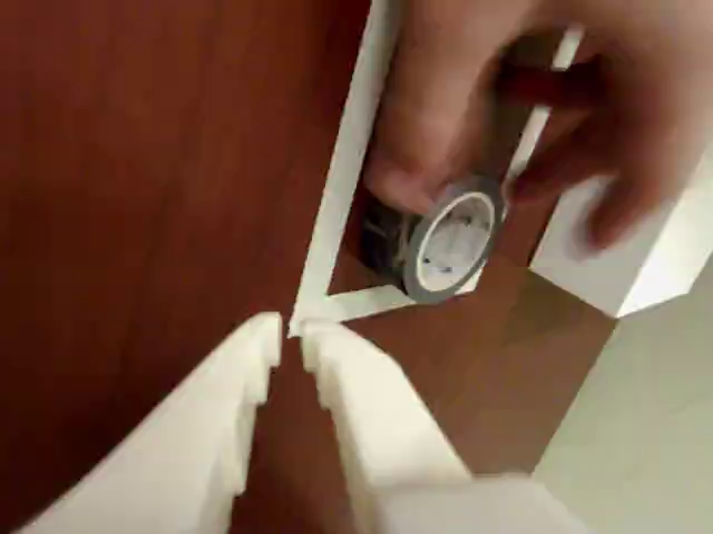
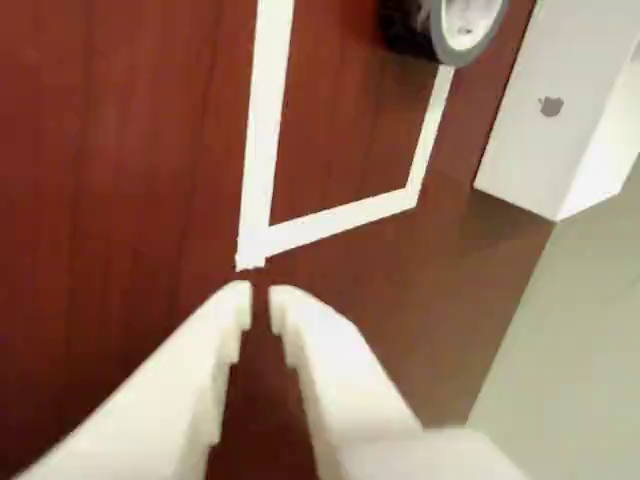
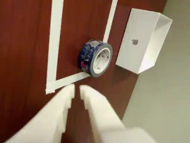
这些图并不漂亮,甚至因为相机安装方向看起来有些歪,但它们比一张专门摆拍的全景更有用。仿真里的相机最终要对齐的是策略实际见过的画面,而不是人的观看习惯。
场景的第一版尺寸来自照片估计,随后改成手工测量值:桌面 720 × 500 mm、厚 25 mm;胶带外径 45 mm、内径 30 mm、高度 20 mm;白色托盘外部 105 × 105 mm,内部 100 × 100 mm,底厚 5 mm、壁高 35 mm。这些值统一写进 YAML,场景资产由脚本生成,避免每次在 GUI 里手调出一个无法复现的新版本。
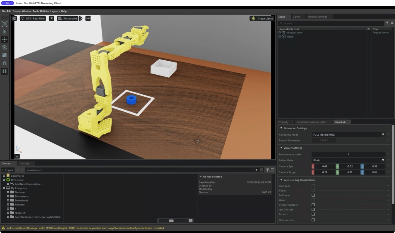
实测尺寸落进场景后,胶带、白框、托盘和机械臂不再只是“看起来差不多”。
先把版本问题关在笼子里
LAB-2 上原本已经有 Isaac Sim 6.0.1,直接在原环境上安装 LeIsaac 很容易把依赖混在一起。这次单独固定了一套环境:LeIsaac v0.4.0、Isaac Lab 2.3 兼容运行时、Isaac Sim 5.1.0、Python 3.11,原来的 6.0.1 目录保留不动。
中间还碰到一个很像“代码坏了”的问题:595 驱动和当前 RTX 渲染链路不兼容。切回 Isaac Sim 5.1 支持的 580 驱动分支后,才继续做下面几道门禁:
- Cartpole 在 RTX 3090 上跑 300 Steps;
- 官方 SO-101 资产通过 120 Steps PhysX 诊断;
- 官方 LiftCube RGB 任务跑 20 Steps,前置相机输出
[1, 480, 640, 3]; - 自定义蓝胶带任务跑 5 Steps,腕部相机同样输出
[1, 480, 640, 3]。
这个顺序看起来慢,却能把“环境装错”“机器人资产错”和“自定义任务错”分开。否则一上来就跑完整抓取,任何报错都会混在一起。
从照片坐标变成世界坐标
第一版场景里,托盘过大,机械臂底座的朝向也和真机不一致。通过 WebRTC 打开远端 Isaac Sim 后,逐项检查 Robot 的平移和旋转,再保存新的基准姿态。
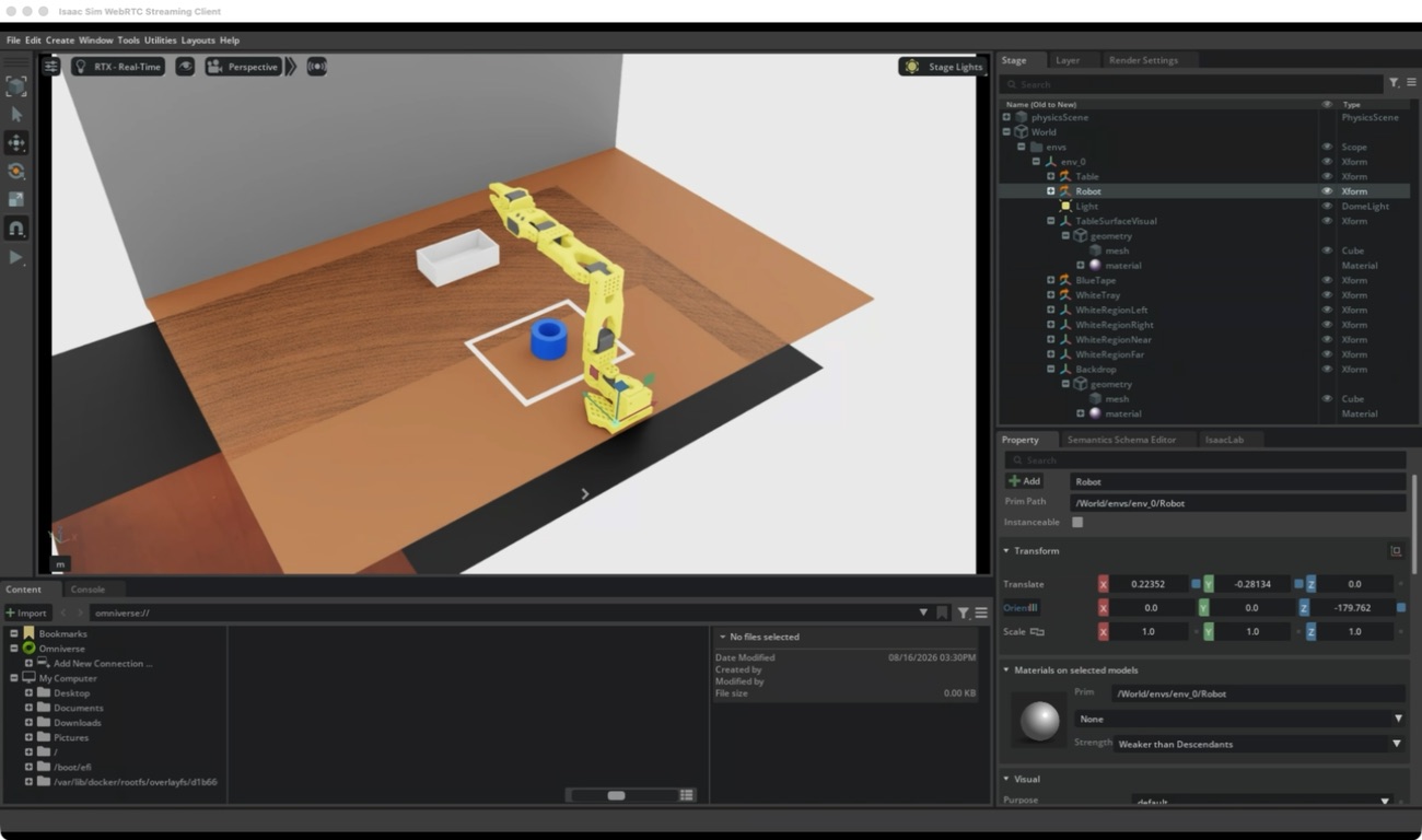
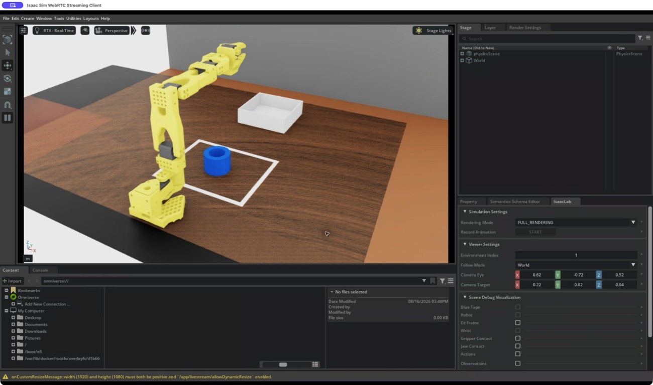
坐标审计最终确认:桌面顶面为 z=0.025 m,胶带碰撞包络为 z=0.025..0.070 m,托盘底面从同一桌面高度开始,误差控制在 1 mm 内。至少在竖直方向上,物体没有悬空,也没有穿进桌面。
看起来夹住了,为什么仍然抬不起来
场景能运行以后,最初的状态机分成接近、闭合、抬升三段。画面里夹爪已经来到胶带两侧,接触传感器也曾同时读到力。
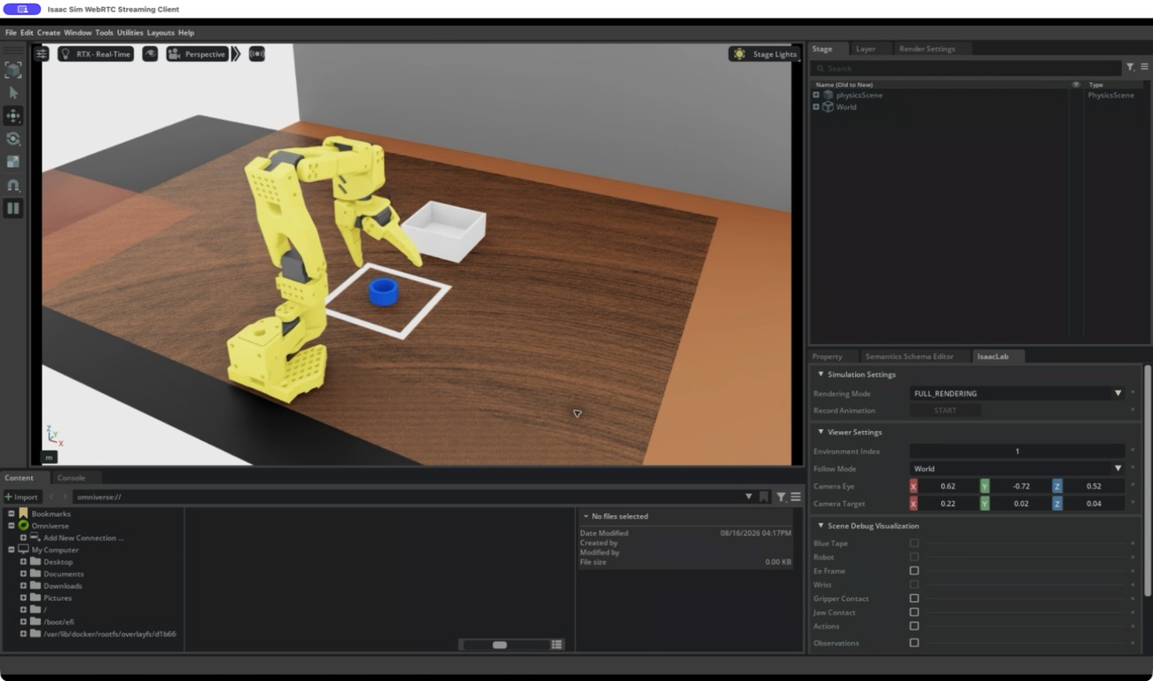
但第一次基线并没有通过抓取门禁:闭合阶段一度双侧接触,进入抬升后却立刻丢掉固定指一侧的接触,最大抬升约 11.09 mm,离 50 mm 的成功阈值还很远。
这时最容易做的,是把摩擦力调大,或者直接给物体加吸附。那会让画面更像成功,却把真实问题藏掉。于是保持胶带质量 0.060 kg、静摩擦 0.70、动摩擦 0.55 不变,先改控制和诊断。
给“抓住”增加一个更严格的定义
新的 Contact Latch 要求固定指和移动指连续 30 个仿真步都检测到经过滤的双侧接触,才停止水平闭合并进入抬升。它把基线闭合漂移从 14.5 mm 降到 9.49 mm,但胶带仍只抬起 8.53 mm。
接着测试了 9 个小范围候选:沿闭合轴、纵向和竖直方向各偏移 ±5 mm,再加 ±5° 偏航。最接近的一组是 vertical_plus_5mm,闭合漂移降到 4.52 mm,但最大抬升只有 4.18 mm;把抬升阶段延长到 300 Steps 也没有改善。
从接触轨迹导出相对姿态后,editor_latch_pose 又把闭合漂移降到 1.28 mm,双侧接触保持了 31 Steps。结果依然没有过门:抬升第一步,固定侧接触变成 0 N,移动侧只剩 0.2946 N,最大高度 2.42 mm。
这组结果把失败范围缩得很小:不是完全碰不到,不是胶带被继续闭合推走,也暂时没有证据说明夹爪在压桌。更像是固定指、移动指和胶带环之间只发生了边缘擦碰,没有形成能在离开桌面后继续承力的夹持包络。
这篇文章没有一个“成功结尾”
目前还没有把仿真任务写成“完成”。三次连续物理成功、五组起点、腕部相机对齐和五分钟 WebRTC 门禁都还没有通过;π0.5、RL 和 Sim2Real 也没有接进来。
下一步不是继续批量扫参数,而是在 Grasp Editor 里显示碰撞体,人工确认胶带根帧、gripper 刚体和移动 jaw 的相对位置。新的验收顺序也会更严格:
双侧闭合接触 30 Steps → 微抬 2–3 mm 并保持 30 Steps → 双侧力仍 ≥ 0.5 N → 再抬 50 mm。
如果微抬阶段仍然掉力,就继续修姿态和碰撞包络,不进入托盘放置和相机验收。仿真的价值正在这里:它没有替真机制造一段更漂亮的视频,而是把“抓不起来”从一句模糊描述,缩小成了一个可以继续验证的物理问题。
NVIDIA Isaac Sim is a simulation platform for robotics development. Built on Omniverse, USD scenes and GPU PhysX, it can place robots, cameras and objects in a virtual environment while simulating joint motion, collisions, contact and sensor data. Problems that would otherwise require repeated real-robot trials can first be observed and recorded here.
The “digital twin” in this article means more than placing a robot model in a scene that looks similar. The real task’s dimensions, coordinates, camera view and contact behavior must also be measurable, reproducible and testable in Isaac Sim. Without those foundations, π0.5, reinforcement learning and Sim2Real would rest on an unverified scene.
ACT and π0.5 had already completed the blue-tape task on the real robot, but real-robot debugging has a natural limit. When the arm jerks, video and joint logs do not immediately reveal whether the policy, controller or gripper contact caused it. The simulator’s first job was not to train another model. It was to turn the pick-and-place task into a physics experiment that could be inspected one step at a time.
Starting from real wrist-camera frames
The 50 π0.5 demonstrations were useful beyond model training. The first frame of each group preserved the tape position, target box and the part of the scene visible to the wrist camera. These are three starting regions from the real dataset.
These frames are not polished, and the camera mounting makes them look rotated. That is exactly why they matter. The simulated camera must eventually match what the policy actually saw, not what looks comfortable to a human viewer.
The first scene used photo-derived estimates, which were then replaced with measurements: a 720 × 500 mm tabletop with 25 mm thickness; a tape roll with 45 mm outer diameter, 30 mm inner diameter and 20 mm height; and a white tray measuring 105 × 105 mm outside and 100 × 100 mm inside, with a 5 mm base and 35 mm walls. The values live in YAML and the assets are generated by script, preventing each GUI adjustment from creating another unreproducible scene.
Once measured dimensions entered the scene, the tape, marked square, tray and robot were no longer only visually approximate.
Isolating the software stack first
LAB-2 already had Isaac Sim 6.0.1. Installing LeIsaac into that environment would have mixed incompatible dependencies, so this experiment pinned a separate stack: LeIsaac v0.4.0, an Isaac Lab 2.3-compatible runtime, Isaac Sim 5.1.0 and Python 3.11. The existing 6.0.1 directory remained untouched.
One early failure looked like broken task code but came from the renderer: the 595 driver was incompatible with this RTX pipeline. After returning to the 580 driver branch supported by Isaac Sim 5.1, the system passed a sequence of gates:
- Cartpole for 300 steps on the RTX 3090;
- A 120-step PhysX diagnostic on the official SO-101 asset;
- Twenty headless steps of the official LiftCube RGB task with a
[1, 480, 640, 3]front-camera observation; - Five clean steps of the custom tape task with the same wrist-camera shape.
The sequence separated environment, robot-asset and custom-task failures. Running the complete grasp first would have mixed all three.
Turning photo coordinates into world coordinates
The first scene used an oversized tray and an incorrect robot-base orientation. Isaac Sim was opened remotely through WebRTC, the Robot transform was inspected, and a new baseline pose was saved.
The coordinate audit then confirmed a tabletop surface at z=0.025 m, tape collision bounds at z=0.025..0.070 m, and a tray bottom beginning on the same surface, all within a 1 mm tolerance. At least vertically, the objects were neither floating nor buried in the table.
It looked grasped—so why did it not lift?
The initial state machine used three phases: approach, close and lift. The gripper reached both sides of the tape, and both contact sensors briefly reported force.
The baseline still failed the grasp gate. Bilateral contact appeared during closure, but the fixed-finger contact disappeared immediately after lift began. Maximum lift was about 11.09 mm, far below the 50 mm acceptance threshold.
The easy response would have been to raise friction or attach the object artificially. That would make the video look more successful while hiding the real error. Tape mass therefore stayed at 0.060 kg, with static friction at 0.70 and dynamic friction at 0.55, while the controller and diagnostics changed instead.
Defining “grasped” more strictly
A new contact latch required 30 consecutive simulation steps of filtered bilateral contact before horizontal closure could stop and lift could begin. It reduced closing drift from 14.5 mm to 9.49 mm, but the tape still lifted only 8.53 mm.
Nine small candidates followed: ±5 mm along the closing, longitudinal and vertical axes, plus ±5 degrees of yaw. The closest result, vertical_plus_5mm, reduced drift to 4.52 mm but lifted only 4.18 mm. Extending the lift phase to 300 steps did not help.
An exported relative pose then produced editor_latch_pose, reducing drift to 1.28 mm and holding the bilateral gate for 31 steps. It still failed immediately after lift began: fixed-side contact fell to 0 N, moving-jaw contact remained at only 0.2946 N, and maximum lift reached 2.42 mm.
The evidence narrowed the failure substantially. This was not a complete lack of contact, continued object pushing during closure, or—based on the current diagnostics—fingers pressing into the table. The likely failure was edge contact between the fixed finger, moving jaw and tape ring rather than a force-closed grasp that could carry load after leaving the table.
This article does not have a successful ending
The simulation task is not marked complete. Three consecutive physics successes, five starting presets, wrist-camera alignment and the five-minute WebRTC gate remain open. π0.5, RL and Sim2Real have not been connected.
The next step is not another blind parameter sweep. Collision shapes must be displayed in Grasp Editor so that the tape root frame, gripper body and moving jaw can be checked together. The next acceptance sequence will also be stricter:
30 steps of bilateral contact → lift 2–3 mm and hold for 30 steps → both sides still ≥ 0.5 N → then lift 50 mm.
If the micro-lift loses contact, the pose and collision envelope need more work before tray placement or camera validation begins. This is the useful part of simulation: it did not manufacture a prettier video of the real task. It reduced “the robot cannot pick it up” to a specific physics problem that can be tested again.